Spray dried dispersions (SDD) can enhance the bioavailability of poorly water-soluble drugs, enabling the oral delivery of actives that would otherwise be delivered by injection.1–3
As drugs with poor water solubility have become more common in the pharmaceutical pipeline and more contract development and manufacturing organisations (CDMOs) enter the market for SDD production, the manufacture of standard SDDs may seem to be reduced to practice.4
However, compounds with increasingly challenging physical properties such as kinase inhibitors and more demanding target product profiles have brought to light the next generation of spray drying manufacturing challenges.5
Key to overcoming SDD challenges is a mechanistic understanding of why the challenges arise and how to engineer process designs that account for and eliminate them. As bioavailability challenged molecules continue to account for the majority of the small molecule pipeline, maintaining a state-of-the-art understanding of spray dried dispersions and other bioavailability enhancing technologies will be of high importance to pharma and biotech innovators.
Innovative formulation strategy introduces an engineering challenge
The key feature of a bioavailability enhanced SDD is its amorphous state (non-crystalline). The amorphous SDD is made by combining a rapid drying process with a stabilising polymer, kinetically trapping the drug molecules into a disordered state before they have time to crystallise.6–8
The physical stability of the SDD is therefore critical: it must remain amorphous during storage as recrystallisation will compromise the bioavailability enhancement achieved.
To ensure good physical stability, formulators will try to maximise the glass transition temperature (Tg) of the SDD, ideally 20 °C or more above the storage temperature. When the Tg is sufficiently greater than the storage temperature, molecules have low mobility and are effectively “locked in place” during storage, preventing recrystallisation.
When an SDD is prepared from a drug and polymer combination, the dispersion Tg is approximately a weighted average of the drug Tg and the polymer Tg and calculated using simple models such as the Gordon-Taylor equation. For many drug candidates, the drug Tg is significantly lower than that of the polymer.
In these instances, the more drug that the SDD contained, the lower its Tg, causing a physical stability risk. To reduce pill burden in high-dose drugs, SDD formulators must balance the need for high active loading with a desire for good physical stability.
Recent work at Lonza by Mudie, et al., describes the use of Eudragit L100 (Evonik), an enteric dispersion polymer with an ultra-high Tg (187 °C) to combat poor physical stability of high active loading SDDs.9,10
By starting with a high-Tg polymer, more drug can be incorporated into the SDD without lowering the Tg too close to the storage temperature.
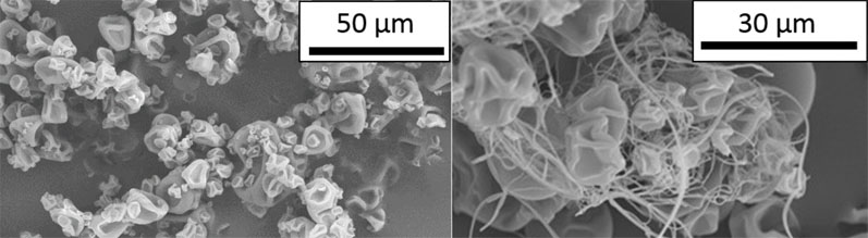
Figure 1: SEM images of spray dried Eudragit L100 morphology without (left) and with (right) filaments
When Eudragit L100 polymer is spray dried, it has been found to produce high-aspect ratio filament particles in addition to the typical spherical or raisin-shaped particles (Figure 1).11 This phenomenon was observed in both placebo or active sprays with different nozzle types and for multiple different solvent systems.
Batches containing significant amounts of filaments had poor yields (<50%), bulk densities lower than 0.05 g/mL and undesirable flow properties.12,13
Filament formation mechanism informs process design strategy
When a spray drying solution is atomised through a pressure-swirl nozzle to form droplets, the droplet formation process consists of three stages (schematically illustrated in Figure 2). First, the sheet ejected from the nozzle forms instabilities owing to surface tension.
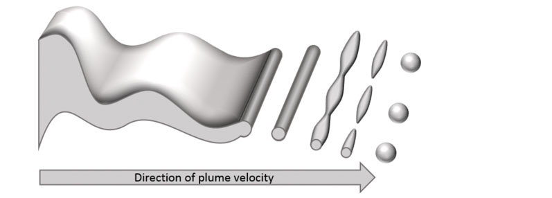
Figure 2: Schematic illustration of droplet formation in pressure-swirl atomisation
When the instabilities reach a critical point, the sheet breaks up into long filaments. Next, instabilities form along the filament axis until break-up occurs a second time. Finally, the liquid stabilises to form spherical droplets.
Filaments form when the characteristic time for droplet break-up exceeds the characteristic time for polymer “skinning,” such that the surface of the particle has cooled and lost sufficient solvent and solidifies. When skinning occurs before droplet break-up is complete, the particle retains its filament geometry.
SEM images in Figure 3 show a filament with the characteristic instabilities forming a “bead on a string” morphology.
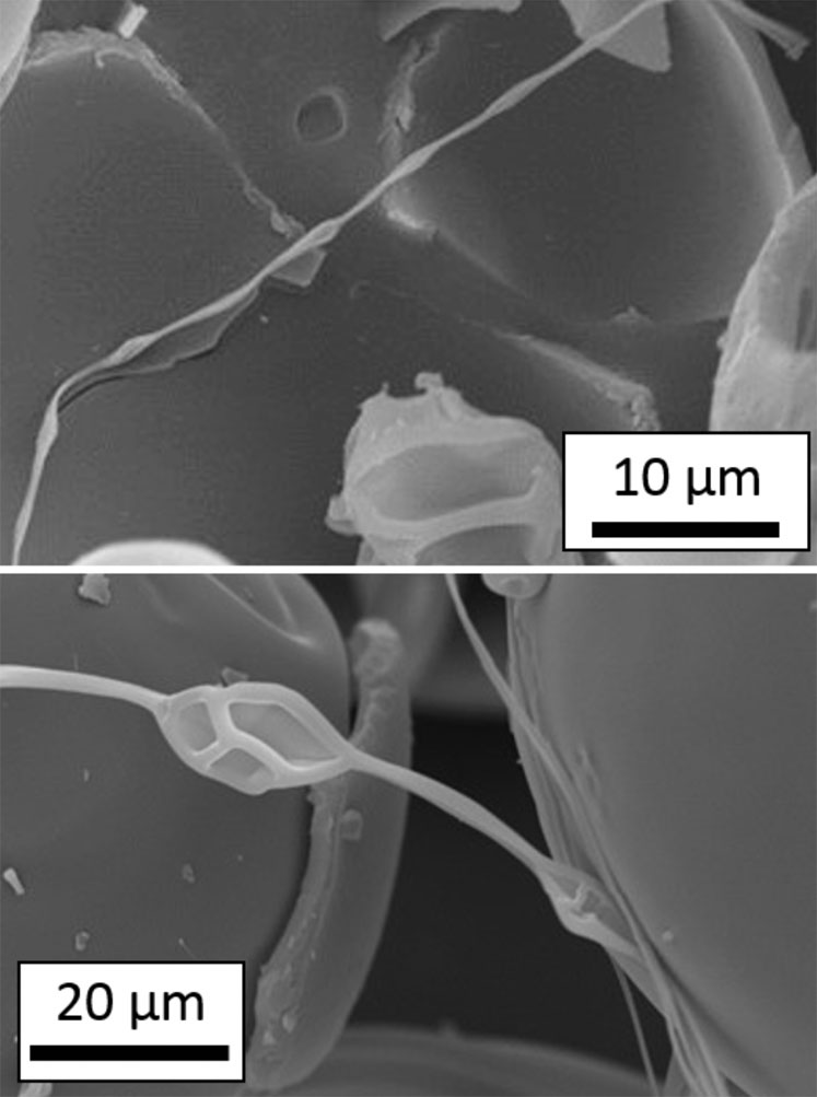
Figure 3: SEM images of filament particles exhibiting a “bead-on-a-string” morphology
With this mechanistic understanding of filament formation, one can rationally design the spray drying process to reliably produce favourable particle morphologies and avoid filaments.
A reduction in inlet temperature, an increase in atomisation pressure and a reduction in spray-solution solids loading all help to decrease filament formation … but for different reasons. A decrease in the inlet temperature, for example, will increase the time to skinning, thereby producing fewer filament particles.
An increase in atomisation pressure will decrease the time to droplet break-up, reducing filament formation. Spray-solution solids loading affects both atomisation and skinning kinetics.
Spray drying process design to control filament formation
By rationally designing spray drying process parameters, the formation of filaments can be avoided during manufacture. This is illustrated here with two examples.
Figure 4 demonstrates the impact of spray dryer inlet temperature on filament formation. At the highest temperature, tangled clusters of filament particles up to 1 mm in diameter were found throughout the sample.
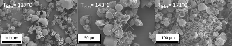
Figure 4: SEM images of spray dried Eudragit L100 powder produced at three increasing inlet temperatures
At the lowest temperature, negligible filament formation was observed. It is therefore preferable to keep the inlet temperature of the drying process moderate by maximising the drying gas flow rate.
Figure 5 demonstrates the impact of spray solution polymer loading on filament formation. As the polymer content is increased, filament formation increases owing to faster droplet skinning.
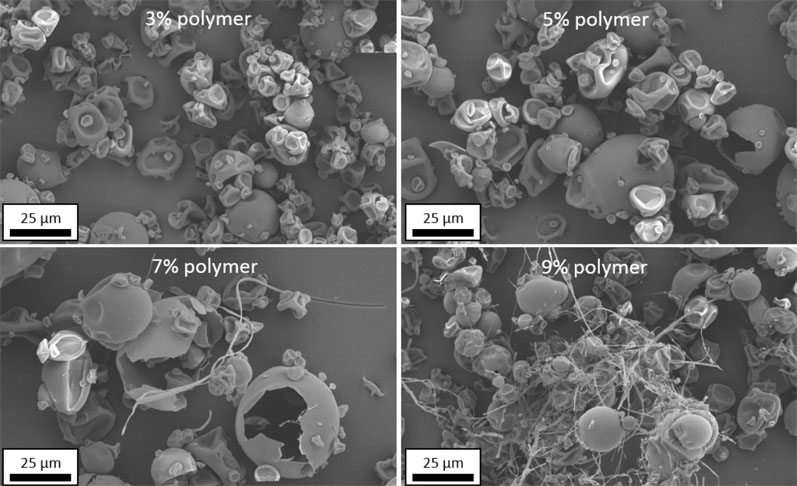
Figure 5: SEM images of spray dried Eudragit L100 powder produced at four increasing spray solution solids loadings
This study spans the range of typical polymer concentrations used in early development through to commercialisation, demonstrating how filament formation may be mitigated during development work with a line-of-sight to commercial production.
However, simply reducing the inlet temperature and solids loading to avoid filament formation is not always possible in a high-throughput process. Additional spray drying process parameters, such as atomisation pressure, solution temperature and drying gas flow rate can be used to design a robust process.12
Process design space and predictive dimensionless parameters
It is of great interest to predict the formation of filaments before spray drying. Three spray drying parameters exhibited the strongest impact of filament formation: solvent volatility (Tboil and Hvap), dryer inlet temperature and spray solution concentration.
Using internal data plus literature case studies, Lonza scientists developed a dimensionless solvent parameter (DSP) that quantifies the risk of filament formation in a spray drying process. The DSP is normalised so that the filament formation cut-off is equal to 1. For a process with good atomisation (a DSP of <1), filament formation is low-risk. As the DSP increases above 1, the risk of filament formation increases (Equation 1).
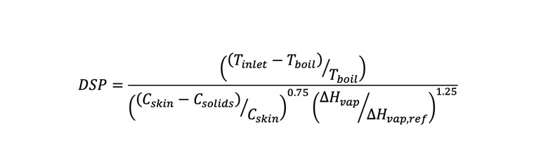
- Tinlet is the inlet temperature of the spray dryer in °C
- Tboil is the boiling point of the spray solvent in °C
- Cskin is the experimentally measured polymer concentration in wt% at which a gelled skin forms on top of a thin film
- Csolids is the polymer concentration in wt% in the spray solution
- ΔHvap is the heat of vaporisation of the spray solvent in J/g
- ΔHvap,ref is the reference heat of vaporisation, 540 J/g
The DSP was calculated for Lonza’s internal data set plus six literature studies and plotted in Figure 6.
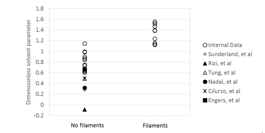
Figure 6: Calculated DSPs for internal spray drying data and six literature studies, categorised by the presence of filaments
The figure shows that for 28 data points, the agreement between the DSP prediction of filament formation and experimental evidence is excellent. The DSP is therefore demonstrated to be an effective means of assessing the risk of filament formation in spray drying.
The above examples are useful to demonstrate the mechanism of filament formation in spray drying plus the DSP as a risk-evaluation tool. To employ these learnings about the interplay between spray drying process parameters and filament formation, Lonza scientists developed process design spaces to identify robust ranges for Eudragit L100 manufacture.
The two-dimensional map in Figure 7 plots two key parameters: spray solution solids loading and inlet temperature for methanol solvent. The shaded area represents the ideal processing space.
The upper boundary for this area is the temperature at which the polymer begins to chemically degrade. The lower limit denotes where solvent removal becomes insufficient, producing SDD with too much residual solvent.
The left-side boundary is an example of acceptable throughput based on process and product requirements. The right-side boundary is the cut-off between negligible and significant filament formation, quantified by the DSP = 1 risk level.
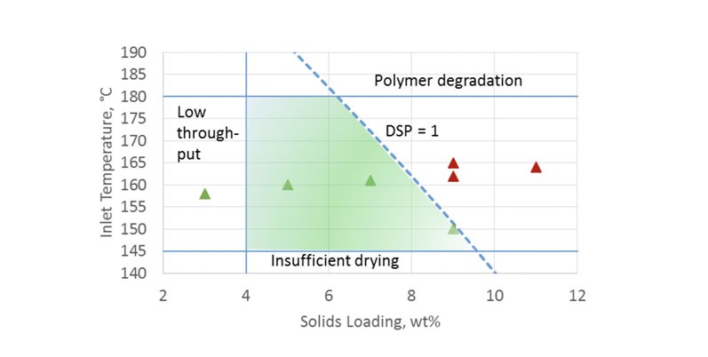
Figure 7: A spray drying process design space for Eudragit L100 spray dried from methanol on a clinical-scale dryer
This process design space was experimentally verified; solid triangles represent spray batches with significant filament formation, whereas open circles represent spray batches with negligible filaments present.
In summary, this work outlined the mechanism by which filament particles form and demonstrated how spray drying process parameters impact filament formation. The dimensionless solvent parameter incorporates the factors with the strongest effects into a risk-assessment tool for Eudragit L100 spray drying.
Exemplifying the impacts of these process parameters experimentally and using literature case studies can show how drug developers may use a mechanistic approach to identify a robust processing space.
Broader impact on spray drying process design
Using the dimensionless solvent parameter, process understanding can be extended to systems that were not tested in this body of work, such as other spray solvents or potentially different polymers.
Although this study was conducted solely with Eudragit L100, the mechanism of filament formation applies in theory to all spray drying systems. Literature reports of filament formation exist for HPMCAS, HPMCP and MAE 100P polymers.12
In spray drying process design, it is common to perform QbD or DoE work to define an ideal operating space for a specific product. This work highlights the advantage of a mechanistic approach to spray drying process design, in which the risk of filament formation can be assessed prior to initiating manufacturing.
This significantly reduces the risk of low spray drying yields and poor powder properties. Rather than empirically testing the limits of the spray drying process, the predictive DSP can be employed to assess risk, thereby improving process outcomes and reducing time to clinic and the amount of active pharmaceutical ingredient required.
References
- D.T. Friesen, et al., “Hydroxypropyl Methylcellulose Acetate Succinate-Based Spray-Dried Dispersions: An Overview,” Mol. Pharm. 5(6), 1003–1019 (2008).
- W.J. Curatolo, J.A.S. Nightingale and S.M. Herbig, “Utility of Hydroxypropylmethyl Cellulose Acetate Succinate (HPMCAS) for Initiation and Maintenance of Drug Supersaturation in the GI Milieu,” Pharm. Res. 26, 1419–1431 (2009).
- S. Huang, et al., “Solubility Advantage (and Disadvantage) of Pharmaceutical Amorphous Solid Dispersions,” J. Pharm. Sci. 105, 3549-3561 (2016).
- S. Gurunath, et al., “Amorphous Solid Dispersion Method for Improving Oral Bioavailability of Poorly Water-Soluble Drugs,” J. Pharm. Res. 6, 476−480 (2013).
- M. Davis and G. Walker, “Recent Strategies in Spray Drying for the Enhanced Bioavailability of Poorly Water-Soluble Drugs,” J. Control. Release 10(269), 110–127 (2018).
- A. Singh and G. Van den Mooter, “Spray Drying Formulation of Amorphous Solid Dispersions,” Adv. Drug Deliv. Rev. 100, 27–50 (2016).
- N. Wyttenbach and M. Kuentz, “Glass-Forming Ability of Compounds in Marketed Amorphous Drug Products,” Eur. J. Pharm. Biopharm. 112, 204–208 (2017).
- S.V. Jermain, C. Brough and R.O. Williams III, “Amorphous Solid Dispersions and Nanocrystal Technologies for Poorly Water-Soluble Drug Delivery: An Update,” Int. J. Pharm. 535(1–2), 379–392 (2018).
- D.M. Mudie, et al., “A Novel Architecture for Achieving High Drug Loading in Amorphous Spray Dried Dispersion Tablets,” International Journal of Pharmaceutics: X 2, 100042 (2020).
- M.M. Morgen, D.M. Mudie and K.B. Shepard, “Solid Dosage Forms with High Active Agent Loading,” US Pat. App. US201862671341P.
- K.B. Shepard and M.M. Morgen, “Controlling the Particle Morphology of Spray Dried Poly(Methacrylic Acid-Co-Methyl Methacrylate) (Eudragit L100) Polymer,” AIChE Annual Meeting (Pittsburgh, PA, US), Abstr. 252C (2018).
- K.B. Shepard, et al., “Impact of Process Parameters on Particle Morphology and Filament Formation in Spray Dried Eudragit L100 Polymer,” Powder Technology 362, 221–230 (2020).
- K.B. Shepard and M.M. Morgen, “Spray Drying Process for Low Aspect Ratio Particles Comprising Poly[(Methyl Methacrylate-Co-(Methacrylic Acid)],” US Pat. App. US201862653852P.