Equilibar back pressure regulators are controlled by varying the loading (reference pressure) within the dome above the diaphragm - this is what controls the flow rates. The significant difference however is that they utilise multiple orifice technology; it’s completely different than the way traditional back pressure valves and back pressure regulators work. The combination of exhaustive design, computer modelling and highly exact engineering combine to offer virtually instantaneous control and unprecedented precision for even the most challenging process conditions.
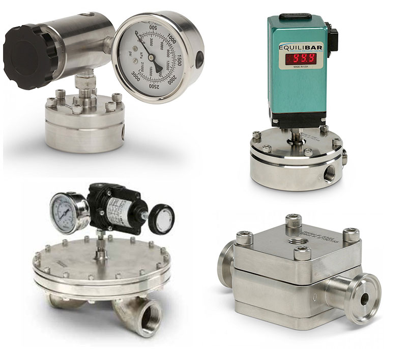
From left to right: 1/16" to 1/4" - Laboratory and Gas Analysis Systems (Research Series), 1/4" to 1" - Gas, Liquid and Mixed Phases (General Service Series), 1 1/2" to 4" - Larger sizes and higher flows (Industrial Service Series), 1/2" to 2" - Biopharma and Hygienic Industry (Sanitary Service Series).
The only moving part within an Equilibar is a supple diaphragm thereby enabling frictionless operation without hysteresis or cracking pressure. Because it is dome-loaded, the balance of forces provides highly reliable, stable back-pressure control. At the same time, the multiple orifice design ensures a huge turn-down range (an ultra-wide flow range) typically 100 times wider than traditional regulators or valves. Within many applications it is possible to reach a turn-down ratio of one million to one. Its novel approach is often a good choice for the researcher or engineer who has already tried conventional pressure control products for difficult process conditions but found then unfulfilling for all their needs.
Inside the Equilibar, the diaphragm is sandwiched between the main body and the reference cap and sealed by O-rings. The main body has parallel orifices that are covered and sealed by the diaphragm when the dome loading (reference) pressure is greater than the process pressure. Every part of the Equilibar including the body, the O-rings and the diaphragm itself can be made from a variety of materials to meet the needs of a particular application.
As mentioned above, the Equilibar is dome loaded and this means that gas or air is fed into the dome (top) area of the regulator to provide the reference, or pressure setpoint, for the process. The pressure of the gas in the dome is set by a secondary standard regulator called a pilot regulator. This pilot regulator can be adjusted manually or electronically, depending on the application’s requirements. As process fluids flow through the unit, the Equilibar holds the process pressure to equal the pilot set point. The diaphragm lifts off the orifices to release pressure as the upstream process pressure exceeds the set-point pressure. When the flow is minimal, only a portion of one orifice will engage to release the pressure. When the flow is high, the diaphragm is pushed up to engage all the orifices. This flexibility accounts for the Equilibar's exceptionally wide flow range.
Traditional back pressure regulators use the increasing overpressure to distort a diaphragm or move a piston to gradually compress a spring that is acting as the set-point. Unfortunately, the compressibility of the spring varies across its range and this change in the spring constant is a major source of error. The Equilibar design eliminates this problem and provides virtually instantaneous control. During operation, the lower pressure at the outlet tries to hold the diaphragm in a leak-tight seal with the orifice; however, even the slightest excess between the fluid inlet pressure and the pilot set-point pressure quickly overwhelms these seating forces and lifts the diaphragm off the orifices. The result is a lightning-fast response, keeping the inlet pressure in tight equilibrium with the setpoint pressure.