To ensure that an exacting volume of insulin is delivered with each pump of a medical infusion device or that a robotic arm used in manufacturing assembly moves to a precise point at the right time, an electric motor has to be combined with an encoder.
A rotary or shaft encoder is an electromechanical device that provides information on the position, count, speed and direction of a motor, and is connected to an application with a controlling device, such as a programmable logic controller (PLC).
The PLC uses the encoder’s information, commonly known as ‘feedback,’ to ensure precise accuracy of motor control.
Encoder technologies
The two main types of encoder are known as incremental and absolute. Incremental encoders identify real-time feedback and track precise motion relating to changes in position and direction, rather than referencing a specific point.
They achieve this by providing feedback on the relative movement between positions with continuous high and low feedback pulses.
Absolute encoders show exact position however their increased complexity makes them more expensive and means that incremental encoders are more cost-effective for most applications.
Adding an incremental encoder interface, such as an Application-specific Integration Circuit (ASIC), can also add exact position reference capability.
An encoder’s sensor usually operates on an optical or magnetic principle. Optical encoders pass infrared light emitted from an LED through a metal code wheel, comprising clear and opaque segments, which create distinct light signals received by optoelectronic sensors.
This technology means that optical encoders are able to create highly accurate, precise positioning. In addition to its high accuracy, the measurement of an optical encoder, such as Portescap’s E9, is unaffected by potential magnetic interference.
The M-sense is a magnetic encoder. This is a single-chip technology that provides three channels of feedback and has an integrated RS422 line driver
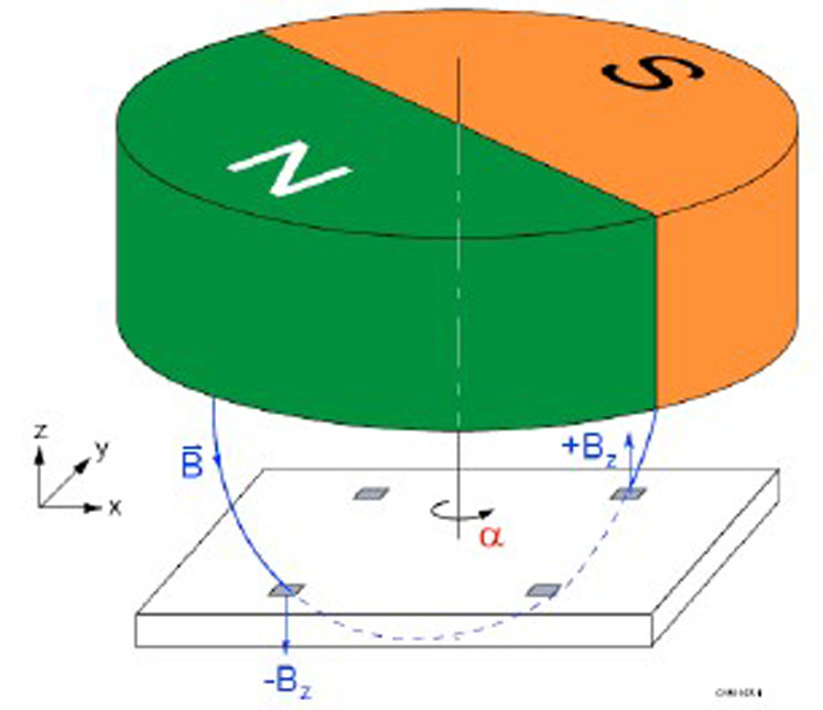
Meanwhile, a magnetic encoder comprises a magnetised disc with a number of poles surrounding the circumference. When the disc rotates, sensors detect the change in magnetic field, such as those measured by Hall effect devices, which monitor the change in voltage.
Magnetic encoders, such as the Portescap MR2, are ideal for use in demanding applications that could include the potential for impact or ingress. The MR2 magnetic encoder, for example, is insensitive to temperature and has low sensitivity to unwanted external fields.
How an encoder works
As the encoder rotates, it generates two square wave outputs, A and B, which are normally 90 degrees out of phase with one another. By measuring the phase shift of the A and B outputs, the encoder’s direction can be determined.
To measure its distance of travel or speed, the encoder’s resolution must also be taken into account. Resolution is the number of points of measurement within one 360 degree revolution of the shaft, also known as the duty cycle or period.
Generally, the greater the number of points, which are termed Lines per Revolution (LPR) or Pulses per Revolution (PPR), the greater the measuring accuracy. For example, Portescap’s M-Sense magnetic encoder has up to 1024 lines per revolution in a compact design.
Each output, A and B, switches between high and low. The two bits of information thereby create four times the counts for each line or pulse and this is known as quadrature decoding.
Thereby, quadrature decoding can increase resolution by up to four times, for example turning the Portescap MR2 encoder’s 512 lines into 2048 counts or angular steps. In addition to the two A and B output channels, a third channel, Z, is sometimes included which can be used to determine the reference position.
Where encoders are used
Understanding how encoders provide feedback for motor control, we can see how their use is crucial across various applications.
Taking our original example of insulin administration, a drug delivery system requires a precise amount of medication dispensed at a specified rate and the encoder is used to confirm that the exacting dose is delivered.
This example also shows how the greater number of lines for increased encoder resolution can help ensure precision to the most exacting rate of flow.
A robotic gripper can be used for example in manufacturing to handle relatively delicate components. It’s key to ensure that the right amount pressure and speed is used to correctly handle the component to avoid damaging it.
Thanks to an encoder, the robotic gripper’s function is optimised by the motion control of its motor’s speed and position, specific to each component it handles.
Similarly, pick and place applications used in the assembly of electronic equipment require high speed motion control to quickly and repeatedly detect the size and weight of PCB components, placing them with precision.
Encoders enable this high speed, high accuracy control to ensure productivity and quality of manufacture.